Project design coordination
Develop the proposed arrangement around the intended use, site dimensions, clear heights and structural design inputs.
 SK ENGINEERING& CONSULTINGComplete PEB Solution
ENGINEERING SOLUTIONS
From the initial layout to coordinated fabrication drawings: give your project a clear technical direction.
Preliminary three-dimensional site arrangement concept for a shed, access road and loading canopy.
View this visual ↗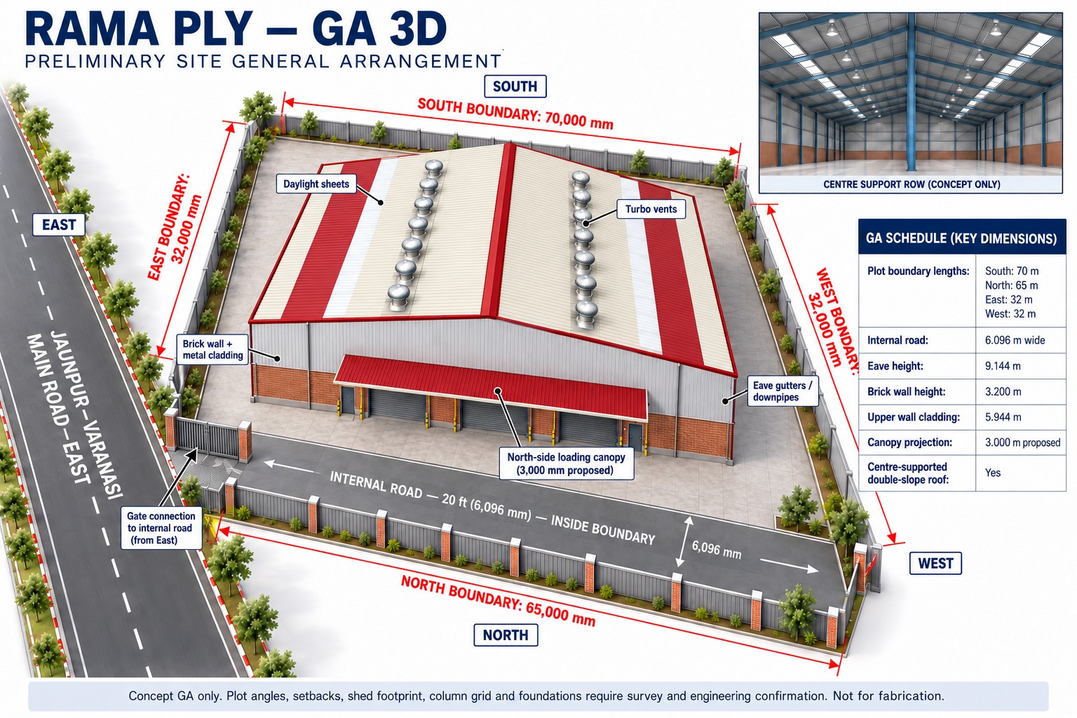
PROJECT FOCUS
A clear drawing package connects the client brief, structural arrangement, workshop requirements and site interfaces. SK Engineering & Consulting brings project planning, drafting and detailing into the same conversation so that the agreed design can be communicated consistently.
SCOPE & COORDINATION
Develop the proposed arrangement around the intended use, site dimensions, clear heights and structural design inputs.
Prepare coordinated plans, elevations and sections with grid references, dimensions and member identification.
Translate the agreed structural design into member, plate, bolt, weld and interface information for review.
Connect workshop drawings, material schedules and erection references through consistent piece marks and revisions.
The client needs a clear layout. Procurement needs quantities. The workshop needs fabrication details. The erection team needs member references. A coordinated drawing package connects these needs through agreed dimensions, design inputs and revision control.
Discuss your project scope ↗THE DRAWING PACKAGE
Define the required drawings and schedules at the start. The package can cover the following items, according to the agreed project scope.
Building grids, column positions, framing layouts, dimensions, elevations and sections to communicate the proposed arrangement.
Individual member geometry, assembly references and piece marks linked to the relevant drawing schedule.
Cut lengths, plate geometry, hole positions, weld notes and connection references based on the agreed design information.
Base-plate, anchor and connection details coordinated with the approved structural design and relevant foundation information.
Section and plate schedules, component quantities and cutting-list information within the agreed drawing scope.
Member-location references, drawing registers and revision identification to keep workshop and site information aligned.
Confirm the drawing inputs, review stages and issue status before fabrication begins. Member sizes, connections and foundation interfaces are detailed against the approved structural design; conceptual gallery images remain visual studies.
IN FOCUS
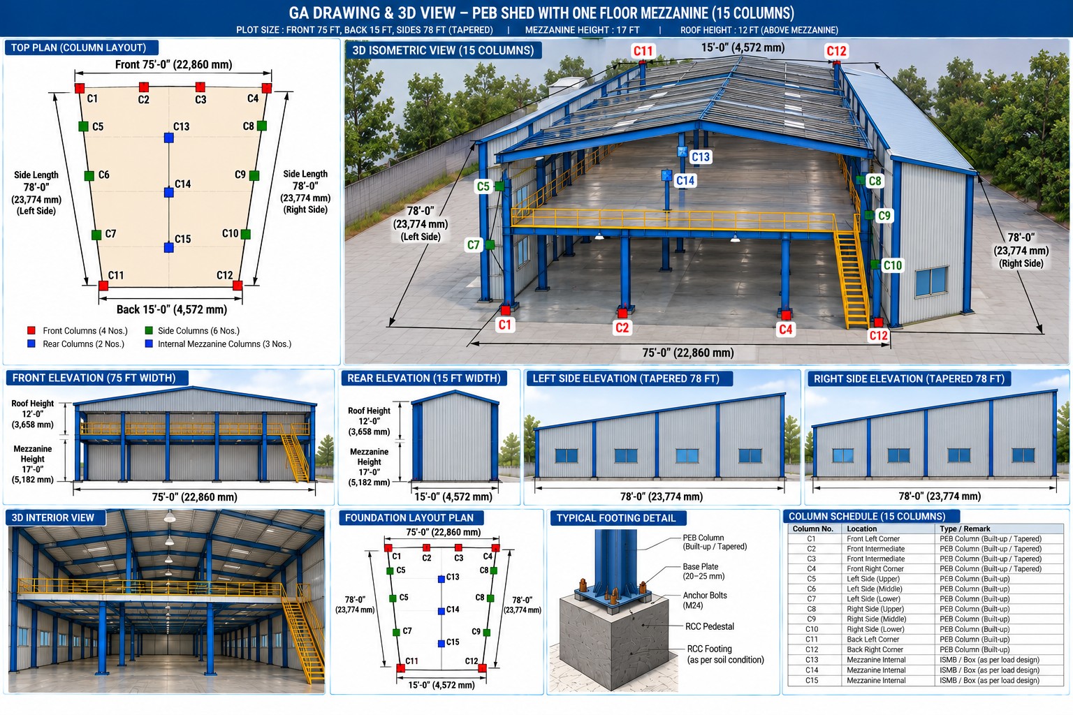
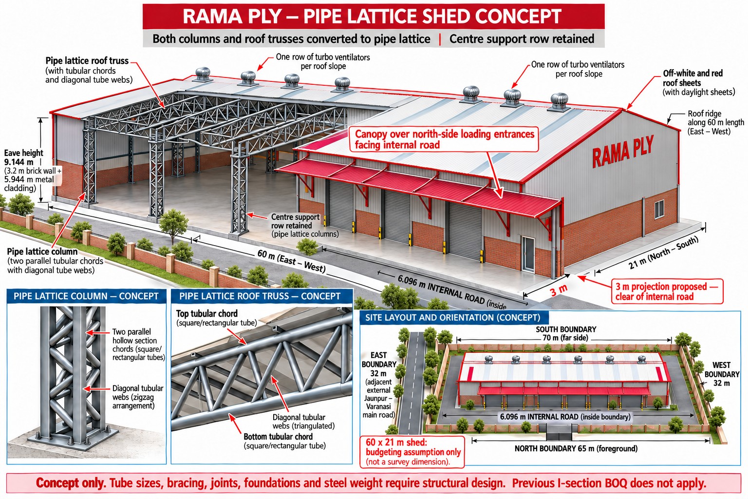
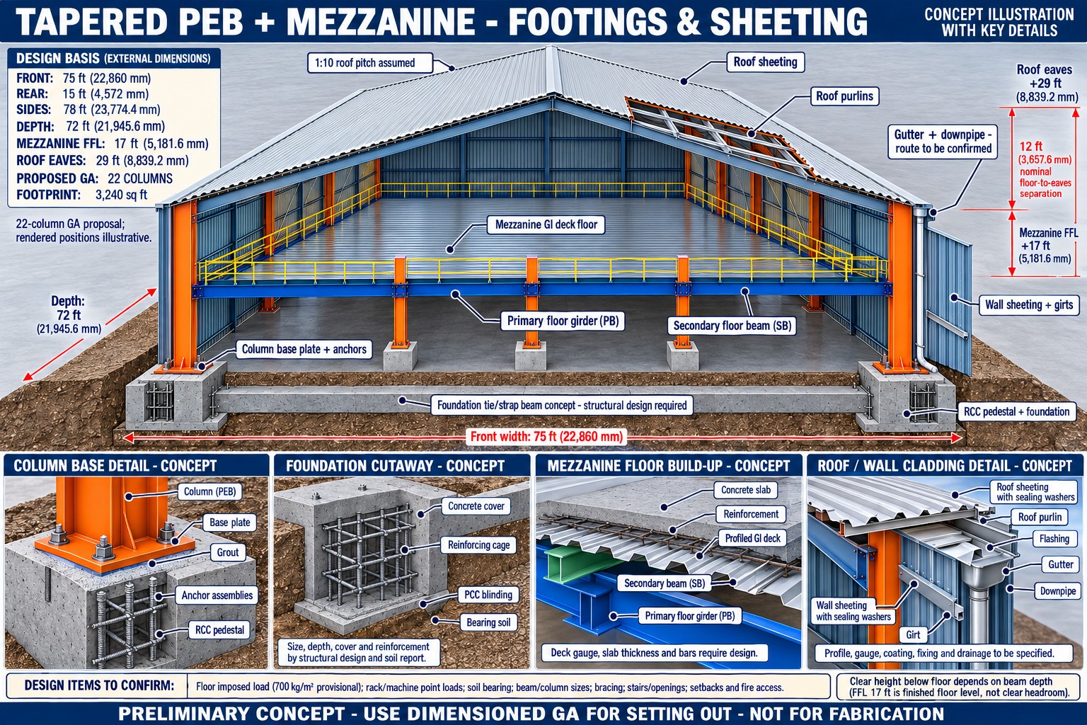
Site photographs, concept drawings and supporting process illustrations are labelled individually. Concepts illustrate proposed options; final project details depend on the agreed design.
START WITH THE RIGHT INFORMATION
Share the following information so we can discuss a scope suited to your project.
LET’S BUILD TOGETHER
Varanasi / Delhi NCR / Mumbai / Ahmedabad / Lucknow
Discuss your location ↗